In situations where a current installation wants to add new sensors for additional coverage, the below instructions should be followed.
Before any works are completed:
- Check installation drawing/live app of the site to see the hub configuration and make sure spare ports are available on the Hub prior to installation
- Identify where the cabling must go to/from
- Identify powerpoints
- Log into App and check the proposed sensor location
Hardware Provided by XY Sense
| Hardware Image | Name | Description |
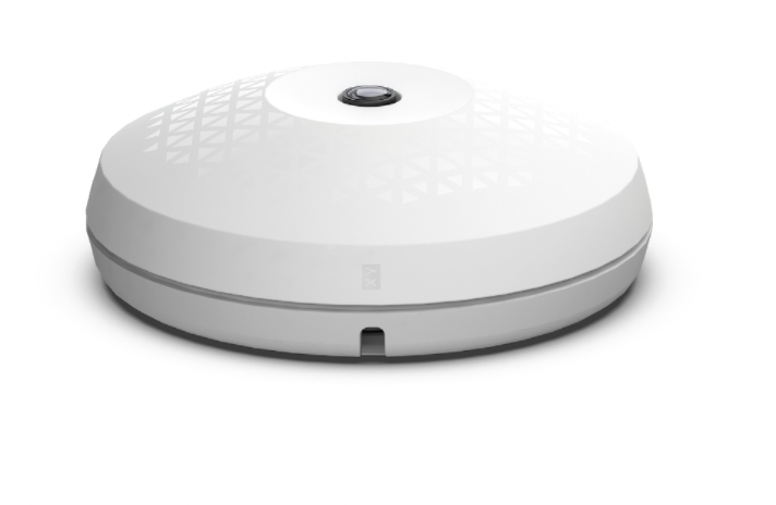 |
XY Sensor |
Flat mounted on the ceiling Contains 2 RJ45 sockets (in/out). Mounted in view of nearby workstations to measure occupancy. Ceiling mount screwed to ceiling substrate via 3 x hollow wall anchors or threaded rod |
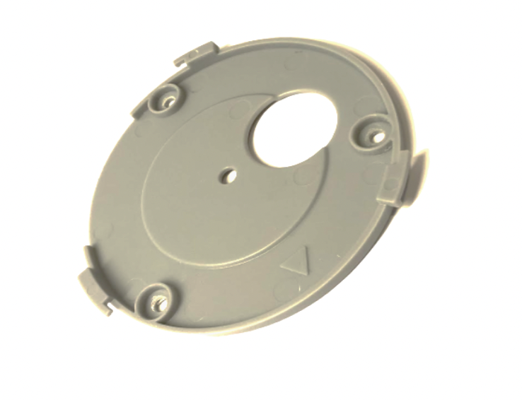 |
Mounting Bracket | Gets installed to the ceiling and the XY Sensor clips to this, provided with each sensor |
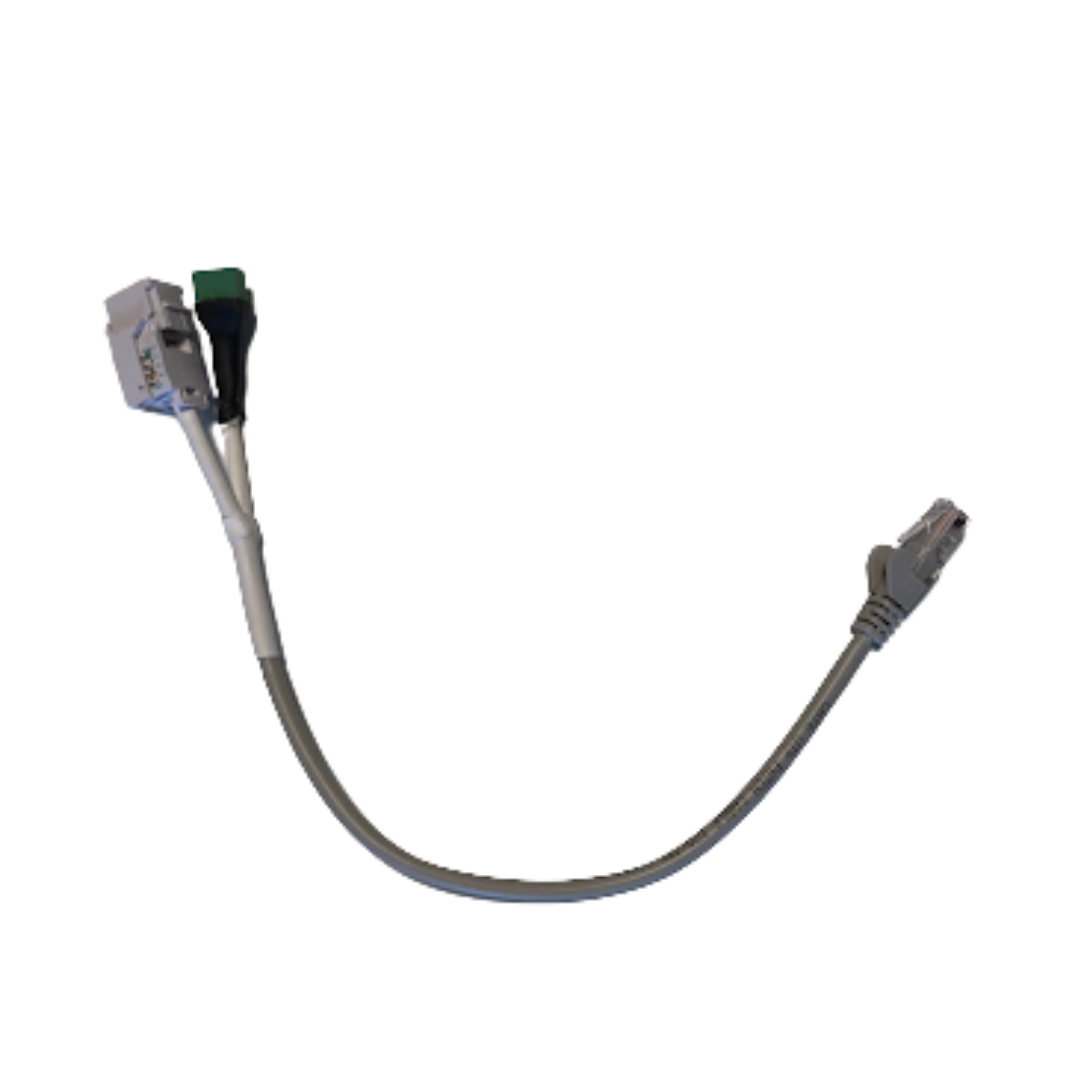 |
V1.0 to v1.1 Adaptor | Connection Adaptor to connect V1.1 Sensor to V1.0 Infrastructure |
Additional Hardware Required
| Additional Cabling |
|
| Hollow Wall Anchor |
|
Equipment
- Drill with 8mm and 20mm bits
- Hollow wall anchor setting tool
- Laptop
- Laser distometer
Installation Method
1. Run Additional Wiring
Run a new wire from the spare ports to cable from the existing configuration to new sensor locations.
- CAT 5e (Or better) UTP, 4-PR, RJ-45 Male Plugs, EIA568A Pinout
- Power Wire: 2-C FIG 8. Flex, 0.75MM unshielded, stripe negative
2. Terminate Cables
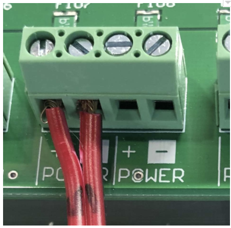
- Figure-8 wire to be connected in “power out” screw terminals inside hub.
- Ethernet cable to be terminated with EIA568A standard.
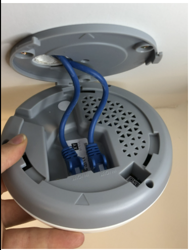
3. Drill Hole & Connect Adaptor
Mark correct location on the ceiling, ensure the ceiling is flat, drill 20mm hole and feed cable through.
Connect Adaptor to old cables. Push excess cabling into the ceiling.
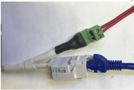
The Adapter once connected looks like this. The single cord from the adaptor should be protruding through the hole in the ceiling.
4. Install bracket
- Use Hollow wall anchors; M4, with substrate thickness of 13mm (plasterboard) or 20mm (tiles), to fix the bracket to roof.
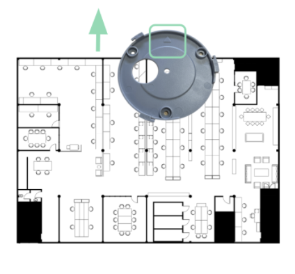
- Locate the arrow on the sensor
- Install all mounting brackets with the arrow directing towards the top of the floor plan (in the portal/on the plans)
- Align all arrows on the bracket to the same direction (this will make step 4 calibration much easier).
- 8mm – wall anchors – qty 3
- 20mm – cable penetration
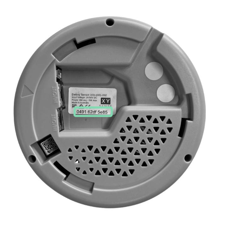
5. Record sensor ID
Record Sensor ID Number (eg. 68271980d185) before attaching the sensor to the bracket
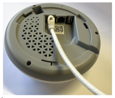
6. Connect adaptor to sensor
Connect Ethernet cable to sensor. Can be plugged into either in/out port.
7. Clip sensor onto bracket
Align arrow on sensor to arrow on roof bracket. Sensor rotates clockwise into the bracket.
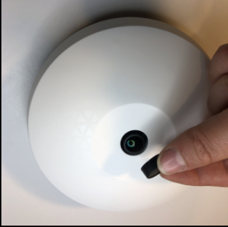
8. Remove lens cap
Please remember to remove the lens cap! Sensor will not work and will need to return to site if these are left on.
Commissioning
1. Login to App
- You will receive an email with your login credentials prior to the installation
- Visit https://app.xysense.io/
TIPS & TICKS: Your account invitation is only active for 7 days after it was sent
please ensure you login within this time frame

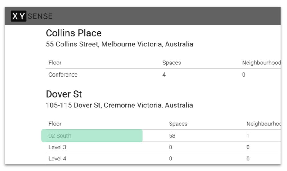
2. Navigate to the correct floor
- Find the correct building address and navigate to the floor or space that is being installed
- Note: “Spaces” and “Neighbourhoods” will likely be “0” for all floors that are not set up. These are features for the end customer to analyse their space utilisation.
3. Retrieve ID from Sensor
- Remember to perform this step before installing in the ceiling
- Sensor ID is found on the XY Sense Sticker under the barcode
- This ID is allocated on a customer basis by XY Sense
- The ID is 9 characters (e.g. 0100036d3 including letters a-f)
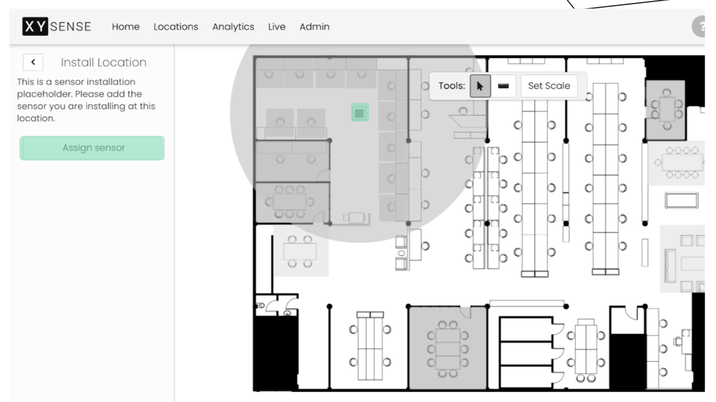
4. Select Sensor Location
- Highlight the grey square showing the sensor location
- Click Assign Sensor
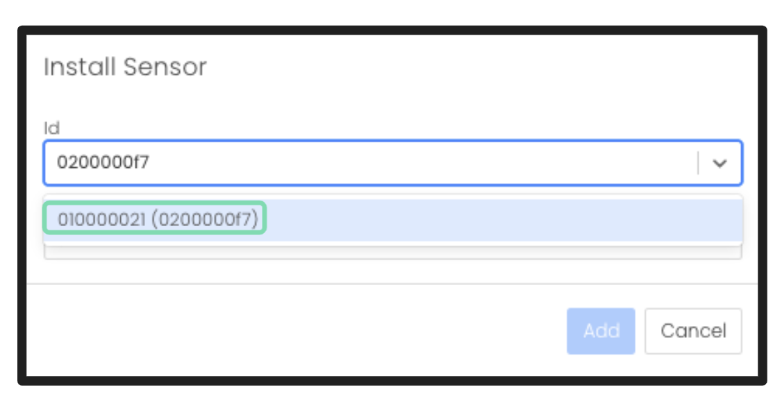
Enter Sensor ID & Height
- Enter the ID from the previous step
- If you enter a valid ID it will show up in the dropdown menu
- If you see “No Results” please double check you have entered the correct ID
TIPS & TICKS: type in the last 4 digits only
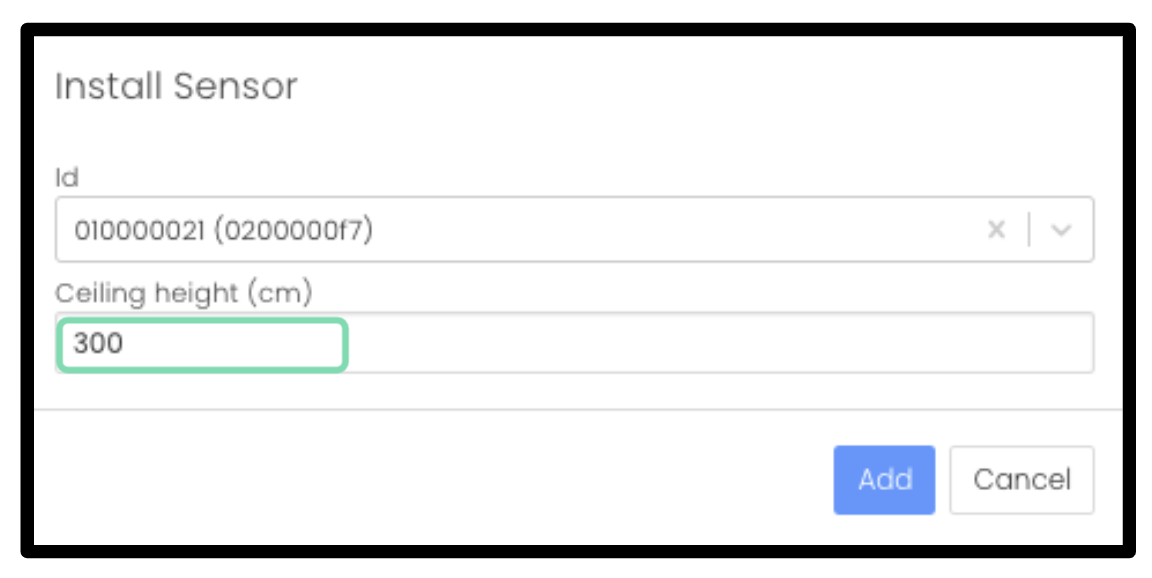
- The ceiling height is the height measured from the floor to the lens (either taken from the floorplan or measured using a laser distometer)
- This value can be used for all sensors on a floor (double-check meeting room heights as they might differ)
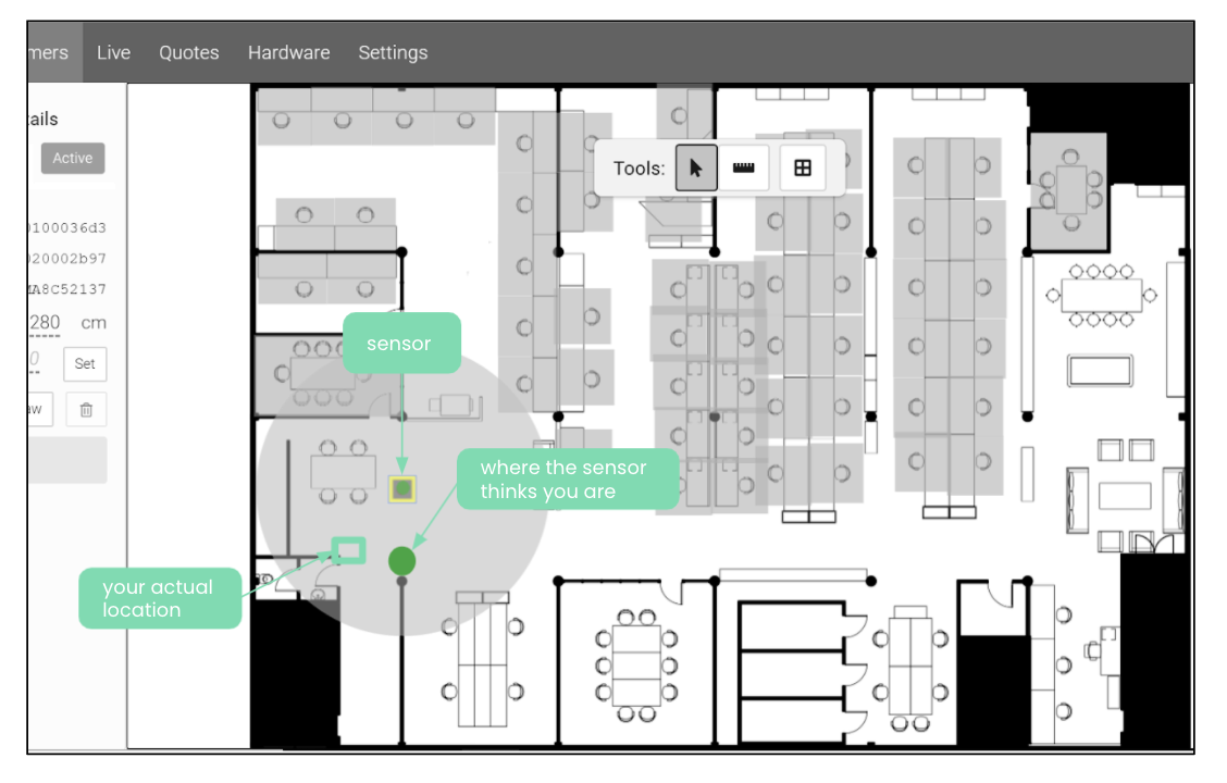
IDENTIFY YOUR LOCATION RELATIVE TO THE SENSOR
- Stand in a fixed position relative to the floorplan and sensor, near something structural rather than furniture
- You should see a consistent green dot appearing which represents your location measured by the sensor
- Ensure the area is clear except for you. You might see random green dots appear, these are errors and can be ignored
- If you see other consistent dots, these might be errors caused by chairs and other objects. Move around to see which dot is you and ignore the others.
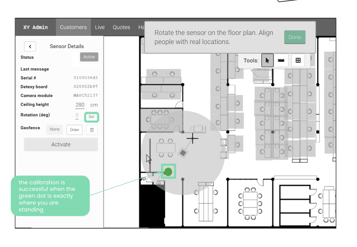
ROTATE THE ANGLE OF THE SENSOR
- Click on “Set”. This allows you to rotate sensor orientation
- Rotate the sensor until the solid green dot appears where you are standing
- Click “Done” once you are satisfied with the calibration
TEST THE LOCATION
- Sit in different seats to ensure accuracy
- Stand at fixed points
- Adjust the rotation as necessary
Comments
0 comments